QUICK START
This chapter will get you acquainted with the architecture of the robot, and concludes with a grasshopper Hello World example that allows you to drive the robot with Rhinoceros.
Layout & Features
A core concept behind this 6 axis robot arm is features. A feature is a 3 axis coordinate space. The robot arm contains two features, one for each trio of axis: A Base feature (Which I am referring to as Global) and a Head feature (Local). You can define new features that are aligned with the surfaces of the working object to localize the coordinates. By nesting coordinates and orientations with features, you can repeat the local commands of a feature while a different feature moves (I.e., head feature space to draw circle, rotating the base to repeat that same drawing of the circle in different points in space.
Unless otherwise defined, the positioning of the robots tip will take place in the global feature.
To create custom feature:
- Define a feature
- Apply that feature to the workpoints when programming.
- You can jog within features. Under the Move tab, in the Feature dropdown at the top right, select the feature relative to the movement you want to achieve.
- You can change the feature coordinate system afterwards, and this will subsequently displace all of the movement commands mapped to that feature.
Electrical Layout
The electrical componentry of the UR-10 are as follows:
- Control Box - Contains the computer and ports
- Motherboard - Contains ethernet connector for wireless (located at bottom of computer box), usb ports for file transfer, and I/O ports for connection to sensors and electronics. -USB connectors (Usb stick only? 4 usb slots)
- Leftmost Yellow connectors - Emergency stop signals. A signal sent through these ports will stop the machine.
- Grey/Yellow Connectors - Safety related, but not necessarily emergency stop, signals (System level?)
- Grey Connectors - Digital signals
- Green connectors - Analog Signals
- Pendant - The attached screen. Note the button located on the back of this screen that allows free movement of the robot when held down. Tool flange - the robot head where end effectors are attached
Initialization
Note - protective stop enabled when pressure is encountered, and you will have to reinitialize.
On powerup you will get an Initialization Message - Hit the start button to unlock brakes
- Once initialized, use the Move Tab To jog or home the robot
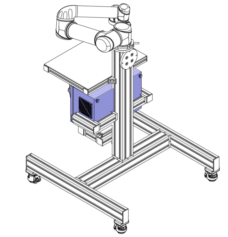
End Effector
The robot needs to be informed of certain properties of the end effector in order to do meaningful work. The end effector of the robot is known as the TCP.
What is the TCP?
TCP stands for Tool center point. When we command the robot to move to a position, the coordinates we specify are that of the TCP. The point should best represent the intersection between the tool head and objects, so that one can avoid unwanted collisions to interface with material as specifically and controlled as possible. For grabbing or multi-pronged tools, the TCP is the center between points of contact on the tool. For nozzles, at the end of the nozzle. For grippers, its the midpoint between the two sides of the gripper. For programming on the pendant, you can specify the tool weight in the following way:
- Click on Program Robot
- Click on Installation
- Click on TCP Configuration
- Click on field labeled “Z”
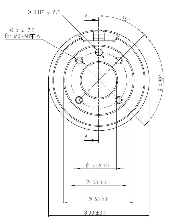
- Needs distance from TCP to the tool flange
- Weigh the end effector
- Add this measurement to the Payload field. Click the Save icon.
- Click the Center of gravity checkbox
- Add the point information for the center of gravity -Example: Payload (.7kg), 11 cm (110 mm) TCP, 2 cm (20mm)
- When done entering properties, click Save Icon
Note - saving, creating new installations/configurations for the robot may require you to restart the robot’s initialization. You will be prompted if this is the case.
Manual TCP Configuration
- Under Program -> Installation -> TCP Configuration, you can use the Position and Orientation buttons to manually set the TCP dimensions and the orientation of the end effector on the robot
- With position, click the position button, set point one, bring the end effector tip to an arbitrary configuration point (I.e. set up a stand with a marker to point at), set. Do this 3 more times from 3 different perspectives on the same point.
- For orientation, before hitting the Set button, use the dropdown that appears after hitting the orientation button and select Base - Align the tool to be parallel with the global Z axis (Straight up from the floor).
Programming the Robot
Polyscope is the built in programming interface and operating system of the robot. The language of communication is URScript.
Example Program Walkthrough
- On the pendant, Click Program
Click Empty Program to create a new program
Note - The program tree is the leftmost box showing the commands in order of sequence and parent/child. Commands are executed sequentially. Note - You can cut and paste commands on the command tree to nest the way you want them to using the on-screen cut and paste buttons.
Click Structure tab to access commands such as move, waypoint, wait, set, etc.
  - Programs consist of waypoints and motion between them.
  - Program tree shows the movements in their order
  - Motion Types
MoveL
Linear motion type, straight line from one point to another. Where the path is important. Suited for motion in confined space.- MoveJ - Fastest between two points. Use where path of TCP is not importantMoveP
Move Process. Maintains a constant speed. Does not stop or make sharp turns - will make filleted corners to maintain a constant speed. Doesn’t slow down when reaching the next waypoint.MoveC
CircleMove - Circle Move - The first point is the starting point, second is Via point (center of arc) end point is end of arc.
Hello World Example
- Create an Empty program
- Open Structure Tab
- Click move
- Under the Command tab, change motion type to whatever is appropriate (Dropdown in top right corner of the command tab)
- You can consolidate all similarly typed movements into one routine. (I.e. two MoveL movements are two waypoints in one MoveL move node)
- A waypoint will automatically be created
- Set waypoint in manual space by clicking on the waypoint in the command tree and set the point’s position
- To create the next movement
- Click the last movement in the tree (not the point)
- Go to structure tab
- Click move
- Click the last movement in the tree (not the point)
- To create a circle move:
- Under the Command tab, you will see a Circle Move option
- Remember, circle moves contain two points (midpoint and endpoint) , with the previous waypoint before the circle move defining the start point of the circle.
Actuation and Sensors
Sensors are attached directly into one of the grey input/output columns located on the robots onboard computer. (One sensor per column)
Under I/O tab, you can examine the sensors that are attached You can use the radio buttons in the Tool Output to actuate You can watch the radio buttons in the Tool Input to see how the sensors (when) are being triggered Wait button under the Structure tab allows you to add a Wait command
- Add a wait command
- Go to command tab - You can specify a waiting option. Select Wait for digital input
Set button will allow you to set an analog or digital output (I.e. actuate a tool)
- Add a set command
- Go to command tab - Set digital output, set tool from dropdown, set High (not sure why?)
- Set the payload
    - If you’re picking up an object, set the payload to the tool + the workpiece weight
- If you’re releasing an object, set the payload to the tool weight only Add a timed wait, which will let the robot wait until the gripper is closed on the object.
- Add a wait command
- Add a timed wait
- Type in the appropriate amount of time for the action
Safety Configuration
Under I/O Setup, you can click the Safety Settings tab to set up to 8 safety points. These points define planes that are perpendicular to the TCP. The robot, under the configuration for that TCP, will not cross these planes. Use this to avoid obstructions when jogging and programming with Polyscope.
Palletizing (Wizards)
- You can use wizards to speed up the workflow for setting up palletizing (and a few other) operations. The Wizards tab is located within the nested field within the Structure tab.
- Choose the pattern “square” to array a placed object within a field.
- 4 corner points will be created for this square. Tell it how many objects exist in each dimension (between one and two and two and three). The four corner points are wound clockwise.
- Set the positions for each of these corners using the robot and the workpiece. This will set the placement of the corner objects in the pallet.
- Now set the approach point (moment above the whole pallet), the pattern point (moment where the workpiece is set on the pallet) and the exit point (where the head leaves the area of the pallet), being mindful of not colliding into previously set workpieces.
- If you have a gripper releasing an object, make sure you add the release command between the patter point and exit point commands
- To loop this process, click the Robot Program on the tree (at the top), go to the Structure tab, click the Advanced Tab (in the nested field) and click Loop. Click the Command tab to configure the loop. Set the loop to loop as many times as you need
Advanced Programming
Palletizing
ITL Robot Hello World from Leland Jobson on Vimeo.
- In the command tree, you can add statements such as conditionals (if, else) to finesse a process.
- You can add an if else statement from the Structure - Advanced tab.
- To edit the if else, click on it in the command tree and open the expression editor.
- Note: High or Hi = True / Lo or Low = False
- Any commands that are nested inside of this conditional will not execute unless the statement is proven true.
- You can also create variables, which you can assign to, such as a counter. You can hook these into other conditionals, for example, to stop the process after executing a set number of times. You can reassign variable values at any time in the process. You can create and assign variables by going to Structure - Advanced - Assignment.
- You can initialize variable values at the top of the tree, where you can select the variables from a dropdown and give them a starting value (I.e. for counters, initialize at 0)
Connecting via Ethernet
Your computer can communicate with the robot via ethernet. The port for communicating with the UR-10 is 30002. Sending instructions to this port will bypass the To communicate with the robot:
- Plug in the robot to the laptop via ethernet
- Set the robot’s Network connection to Static Ip
Use the arbitrary address 192.168.1.1 with a subnet mask of 255.255.255.0
- Your computer should recognize the ethernet connection to the robot. It may display the state of the connection as “Not connected to internet”, but this does not necessarily mean that there is not a connection.
- On your computer, under Network and Sharing center (or some other network screen), examine the ethernet connection. Hit “Details…” and take note of the IPv4 settings assigned to the connection
Grasshopper Hello World
We use Scorpion, a free plugin for grasshopper, to perform simple actions with the robot through rhinoceros. You can download scorpion here.
Note: You may need to also install GHPython if you haven't already.
Download the package and install. Open the example file in Grasshopper.
What the grasshopper components do is turn your geometry into robot commands (strings of text) and send them over a TCP/IP socket with unicode 8 encoding (Not to be confused with the robot's TCP).
A sample of the grasshopper output is the following:
def myprog():
  socket_open("192.168.2.3",30003)
  set_tcp(p[0.000000, 0.000000, 0.100654, 0.000000, 0.000000, 0.000000])
  movej([2.756165, -1.950960, -1.842570, 2.222735, -1.570796, -0.385427],a=0.053000,v=0.150000,r=0.000000)
  movel(p[-0.462883, 0.323050, 0.105461, -2.221441, 2.221441, 0.000000],a=0.053000,v=0.150000,r=0.015000)
  movel(p[-0.462883, 0.263218, 0.077366, -2.221441, 2.221441, 0.000000],a=0.053000,v=0.150000,r=0.015000)
  movel(p[-0.462883, 0.196714, 0.078182, -2.221441, 2.221441, 0.000000],a=0.053000,v=0.150000,r=0.015000)
  movel(p[-0.462883, 0.132118, 0.095136, -2.221441, 2.221441, 0.000000],a=0.053000,v=0.150000,r=0.015000)
  movel(p[-0.462883, 0.069420, 0.118312, -2.221441, 2.221441, 0.000000],a=0.053000,v=0.150000,r=0.015000)
  movel(p[-0.462883, 0.006956, 0.142123, -2.221441, 2.221441, 0.000000],a=0.053000,v=0.150000,r=0.015000)
  movel(p[-0.462883, -0.056943, 0.161648, -2.221441, 2.221441, 0.000000],a=0.053000,v=0.150000,r=0.015000)
  movel(p[-0.462883, -0.123141, 0.169585, -2.221441, 2.221441, 0.000000],a=0.053000,v=0.150000,r=0.015000)
  movel(p[-0.462883, -0.187760, 0.154651, -2.221441, 2.221441, 0.000000],a=0.053000,v=0.150000,r=0.015000)
  movel(p[-0.462883, -0.239601, 0.113215, -2.221441, 2.221441, 0.000000],a=0.053000,v=0.150000,r=0.015000)
  stopj(1)
end
Note the different commands shown above:
def myprog():
Tells the interpreter that the below code is the program.socket open
Opens a connection to the robot at the expected socket (30002 or 30003) which is hard coded inside of the robots firmwaremovej, movep, movel
Movement commands with their orientations and speedsstopj
Stop movementend
End the defined program. If there is another program that follows, it will execute.
Set the IP Address

At the top left corner of the definition, set the IP address assigned in the above step "Connecting Via Ethernet"
Set a toolpath

The input for the solver is a collection of planes, each corresponding to the orientation of the end effector in the sequence you want to move.
Have an end effector? Add the geometry to the TCP component
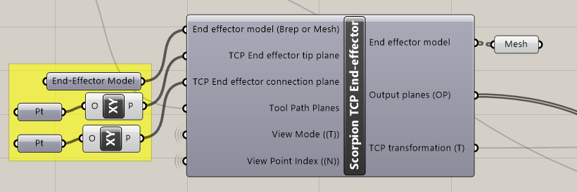
If you have an end effector installed, you will need to model the geometry in rhino and link it to the grasshopper definition via the TCP component.
Enable Feedback
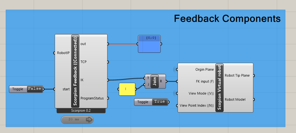
Scorpion comes with a feedback component that provides the position of the robot at a given moment. To receive constant feedback, connect a timer to the component and set it to the appropriate interval.
Send the program
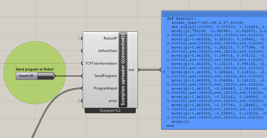
Once you're set up with the above steps, from Connection to implementing your toolpath, you will be able to send a string of commands directly to the machine.
Writing with a Penholder
ITL Robot Penholder Hello World from Leland Jobson on Vimeo.